Home

nagyobbítás fiú hazug diode emulation mode hőség gőzös Bizalmas

Modeling Strategies for a Buck DC-DC Converter

Synchronous Buck Converter Overview - Developer Help

Figure 3 from Comparative analysis of power stage losses for synchronous  Buck converter in Diode Emulation mode vs. Continuous Conduction Mode at  light load condition | Semantic Scholar
Figure 3 from Comparative analysis of power stage losses for synchronous Buck converter in Diode Emulation mode vs. Continuous Conduction Mode at light load condition | Semantic Scholar

CSD95373AQ5M: body diode during DEM - Power management forum - Power  management - TI E2E support forums
CSD95373AQ5M: body diode during DEM - Power management forum - Power management - TI E2E support forums

Figure 8 from Adaptive zero-current switching control scheme for diode  emulation operation | Semantic Scholar
Figure 8 from Adaptive zero-current switching control scheme for diode emulation operation | Semantic Scholar
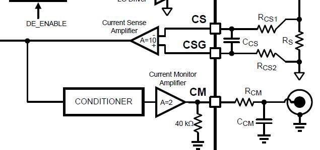
LM5117-Q1: What will be CM output of LM5117 in DCM mode, with diode  emulation enabled? - Power management forum - Power management - TI E2E  support forums
LM5117-Q1: What will be CM output of LM5117 in DCM mode, with diode emulation enabled? - Power management forum - Power management - TI E2E support forums
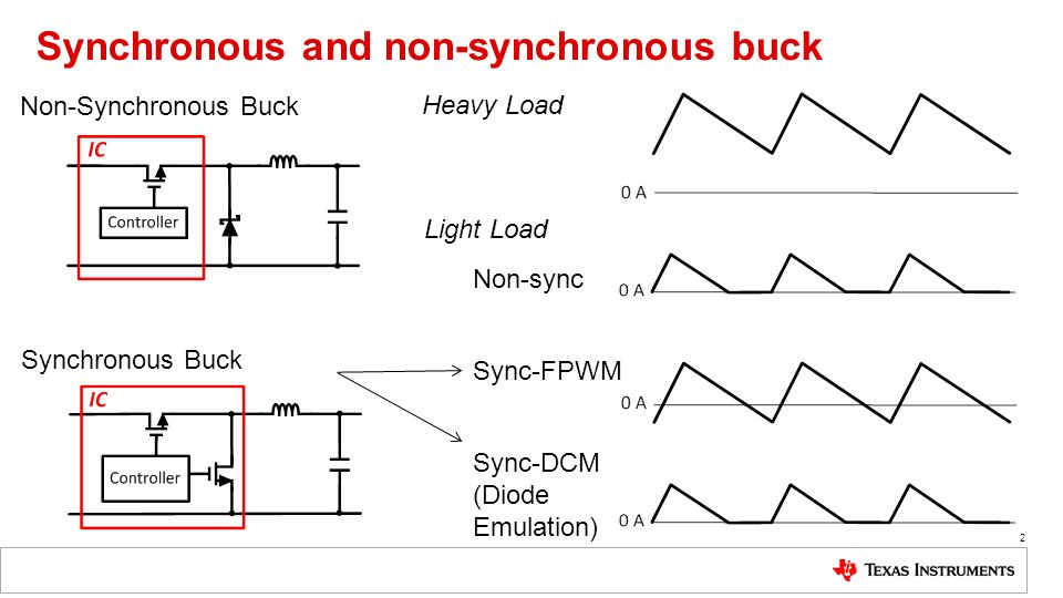
Comparing Synchronous to Non-Synchronous Converters Comparing Size, Cost,  Efficiency, & More Anston Lobo Texas Instruments ppt download
Comparing Synchronous to Non-Synchronous Converters Comparing Size, Cost, Efficiency, & More Anston Lobo Texas Instruments ppt download

LM5116 Datasheet | National Semiconductor - Datasheetspdf.com

Synchronous Buck Converter Overview - Developer Help

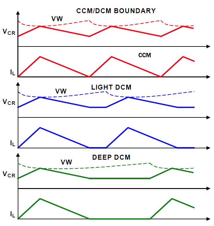
Improving Buck Converter Light-Load Efficiency

Adaptive zero-current switching control scheme for diode emulation  operation | Semantic Scholar
Adaptive zero-current switching control scheme for diode emulation operation | Semantic Scholar

Diode Emulation in DC-DC Converter Part 2- Forced Continuous Conduction Mode  (FCCM) - YouTube
Diode Emulation in DC-DC Converter Part 2- Forced Continuous Conduction Mode (FCCM) - YouTube

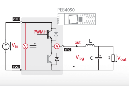
Step-down buck converter - imperix power electronics

Comparative analysis of power stage losses for synchronous Buck converter  in Diode Emulation mode vs. Continuous Conduction Mode at light load  condition | Semantic Scholar
Comparative analysis of power stage losses for synchronous Buck converter in Diode Emulation mode vs. Continuous Conduction Mode at light load condition | Semantic Scholar

NCP81380 - Integrated Driver and MOSFET

Improving Buck Converter Light-Load Efficiency

VOLTAGE REGULATOR INCLUDING QUASI TRANSITION DIODE EMULATION MODE OF  OPERATION - diagram, schematic, and image 04
VOLTAGE REGULATOR INCLUDING QUASI TRANSITION DIODE EMULATION MODE OF OPERATION - diagram, schematic, and image 04

LM5116 Wide Range Synchronous Buck Controller (Rev. G)

VOLTAGE REGULATOR INCLUDING QUASI TRANSITION DIODE EMULATION MODE OF  OPERATION - diagram, schematic, and image 02
VOLTAGE REGULATOR INCLUDING QUASI TRANSITION DIODE EMULATION MODE OF OPERATION - diagram, schematic, and image 02

How does diode emulation work? - Quora

Diode Emulation in DC-DC converter Part 1- Synchronous & Asynchronous  converter CCM mode - YouTube
Diode Emulation in DC-DC converter Part 1- Synchronous & Asynchronous converter CCM mode - YouTube

Electronics | Free Full-Text | Simple and Low-Cost Photovoltaic Module  Emulator
Electronics | Free Full-Text | Simple and Low-Cost Photovoltaic Module Emulator

R3™ Modulation Technology | Renesas

Figure 2 from Comparative analysis of power stage losses for synchronous  Buck converter in Diode Emulation mode vs. Continuous Conduction Mode at  light load condition | Semantic Scholar
Figure 2 from Comparative analysis of power stage losses for synchronous Buck converter in Diode Emulation mode vs. Continuous Conduction Mode at light load condition | Semantic Scholar
Improving Buck Converter Light-Load Efficiency

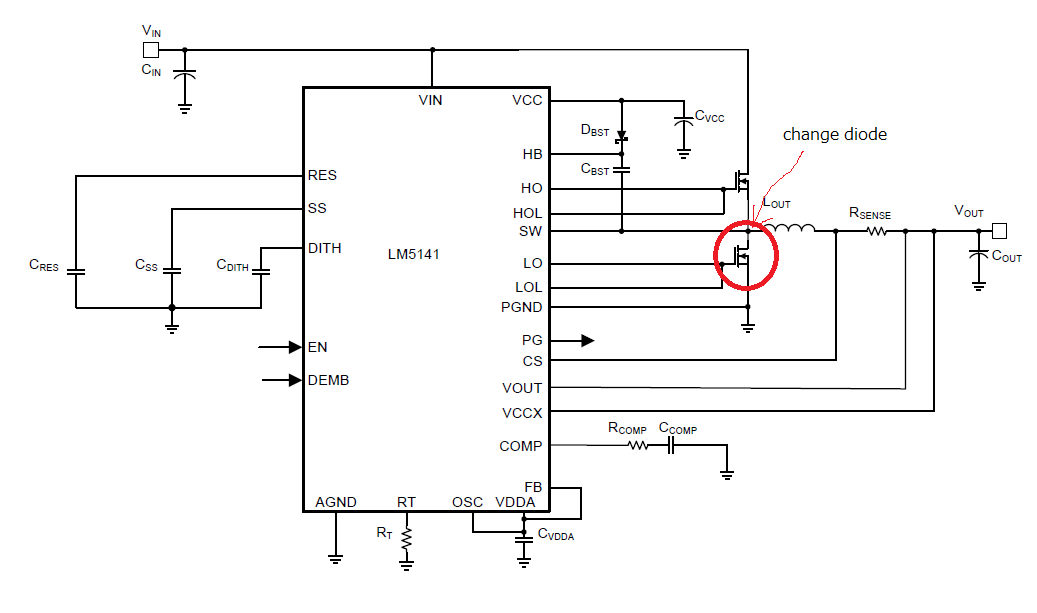
LM5141: Change low-side FET to diode and use in asynchronous circuit -  Power management forum - Power management - TI E2E support forums
LM5141: Change low-side FET to diode and use in asynchronous circuit - Power management forum - Power management - TI E2E support forums

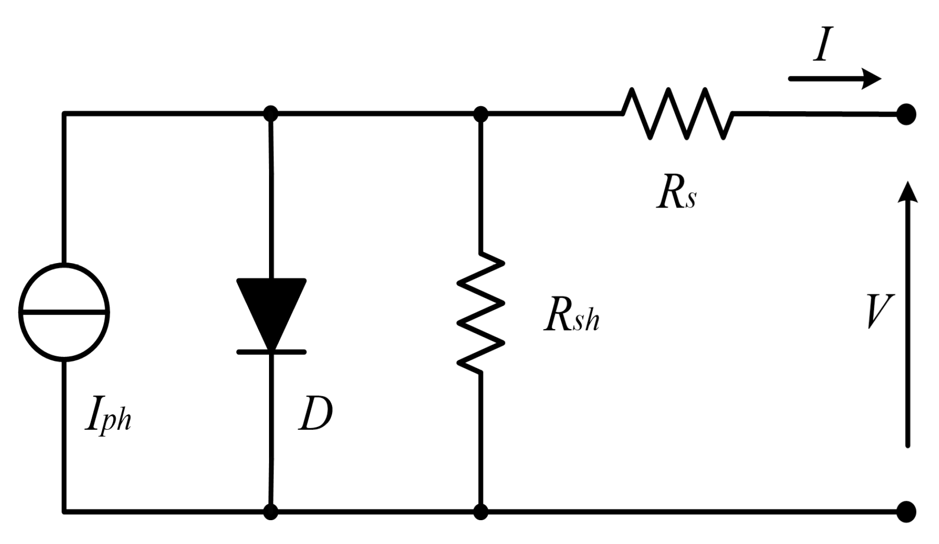
A simple PV emulator using the idea of the one‐diode equivalent circuit...  | Download Scientific Diagram
A simple PV emulator using the idea of the one‐diode equivalent circuit... | Download Scientific Diagram

Simulate MOSFET-Based Ideal Diode | Full Electronics Project